
| Share On: | |
|---|---|
| Categories: | tGW-700 and GW-2200 Series Modbus TCP to RTU/ASCII Device Servers | Modbus Converters and Gateways | Modbus Converters |
| Review: | Write your review |
| Resources: |

Modbus has become a de facto standard industrial communication protocol, and is now the most commonly available means of connecting industrial electronic devices. Modbus allows for communication between many devices connected to the same RS-485 network, for example, a system that measures temperature and humidity and communicates the results to a computer. Modbus is often used to connect a supervisory computer with a remote terminal unit (RTU) in supervisory control and data acquisition (SCADA) systems.
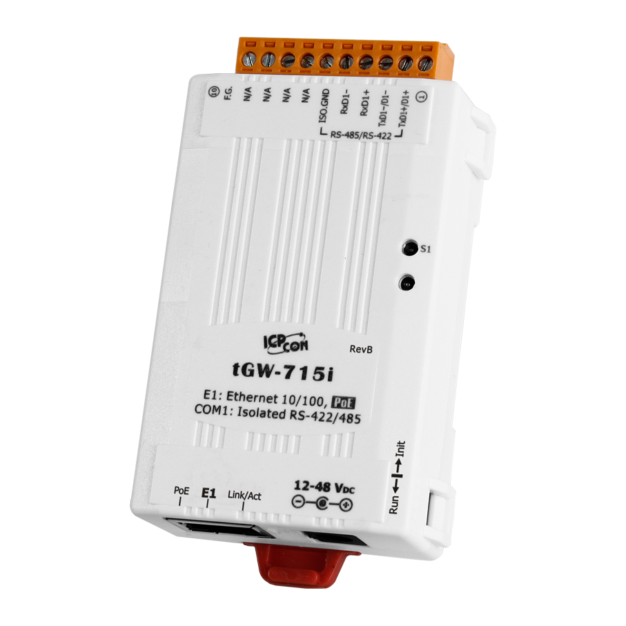
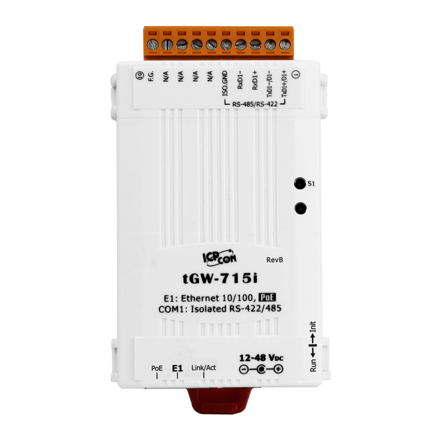
The tGW-715i is an isolated Modbus TCP to RTU/ASCII gateway that enables a Modbus/TCP host to communicate with serial Modbus RTU/ASCII devices through an Ethernet network, and eliminates the cable length limitation of legacy serial communication devices. The module can be used to create a pair-connection application (as well as serial-bridge or serial-tunnel application), and can then route data over TCP/IP between two serial Modbus RTU/ASCII devices, which is useful when connecting mainframe computers, servers or other serial devices that use Modbus RTU/ASCII protocols and do not themselves have Ethernet capability.
DHCP minimizes configuration errors caused by manual IP address configuration, such as address conflicts caused by the assignment of an IP address to more than one computer or device at the same time. The tGW-715i module supports the DHCP client function, which allows it to easily obtain the necessary TCP/IP configuration information from a DHCP server. The module also contains a UDP responder that transmits its IP address information in response to a UDP search from the eSearch utility, making local management more efficient.
The tGW-715i module features a powerful 32-bit MCU to enable efficient handling of network traffic, and also has a built-in web server that provides an intuitive web management interface that allows users to modify the configuration of the module, including the DHCP/Static IP, the gateway/mask settings and the serial port settings.
The module contains a dual watchdog, including a CPU watchdog (for hardware functions) and a host watchdog (for software functions). The CPU watchdog automatically resets the CPU if the built-in firmware is operating abnormally, while the host watchdog automatically resets the CPU if there is no communication between the module and the host (PC or PLC) for a predefined period of time (system timeout). The dual watchdog is an important feature that ensures the module operates continuously, even in harsh environments.
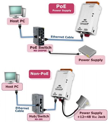
The tGW-715i module offers true IEEE 802.3af-compliant (classification, Class 1) Power over Ethernet (PoE) functionality using a standard category 5 Ethernet cable to receive power from a PoE switch such as the NS-205PSE. If there is no PoE switch on site, the module will also accept power input from a DC adapter. The tGW-715 module is designed for ultra-low power consumption, reducing hidden costs from increasing fuel and electricity prices, especially when you have a large number of modules installed. Reducing the amount of electricity consumed by choosing energy-efficient equipment can have a positive impact on maintaining a green environment.
The module is equipped with a male DB-9 or a removable terminal block connector to allow easy wiring. Based on an amazing tiny form-factor, the tGW-715i achieves maximum space savings that allows it to be easily installed anywhere, even directly embedded into a machine. It also supports automatic RS-485 direction control when sending and receiving data, thereby improving the stability of the RS-485 communication.


| CPU Module | |
|---|---|
| CPU | 32-bit ARM |
| Ethernet | |
|---|---|
| Ports | 10/100 Base-TX, 8-pin RJ-45 x 1, (Auto-negotiating, Auto-MDI/MDIX, LED indicator) PoE (IEEE 802.3af, Class 1) |
| COM Ports | |
|---|---|
| Ports | 1 x RS-485/422 (3000VDC Signal Isolation) |
| Baud Rate | 115200 bps Max. |
| Bias Resistor | Yes, 1 K |
| Parity | None, Odd, Even, Mark, Space |
| Data Bit | 5, 6, 7, 8 |
| Stop Bit | 1, 2 |
| Node Address | 254 (max.) |
| Power | |
|---|---|
| Consumption | 0.07 A @ 24 VDC |
| Powered from PoE | IEEE 802.3af, Class 1 |
| Powered from Terminal Block | +12 ~ 48 VDC |
| Mechanical | |
|---|---|
| Casing | Plastic |
| Dimensions (mm) | 52 mm x 95 mm x 27 mm (W x H x D) |
| Installation | DIN-Rail Mounting |
| Environment | |
|---|---|
| Operating Temperature | -25 ~ +75 °C |
| Storage Temperature | -30 ~ +80 °C |
| Humidity | 10 ~ 90% RH, non-condensing |
Yes. The tGW-715i supports up to 32 TCP connections (masters) per serial port, according to the manufacturer’s tGW-715i specification.
This allows multiple systems, such as an HMI, SCADA workstation, and data logging application, to access serial Modbus equipment through one gateway.
However, multiple TCP connections do not create additional physical serial bandwidth. Requests that need to use the same serial port still have to be managed across the shared serial interface.
Troubleshooting Tip: If each master works independently but response times deteriorate when all are active, test the system with fewer concurrent requests. Check serial bus utilization, queue timeouts, polling rates, and cache settings before assuming the gateway has failed.
The gateway provides several timing parameters on its Port1 configuration page. These control how long the module waits for a response, identifies serial message boundaries, and manages requests waiting to use the serial port.
300 ms
Maximum wait for the serial slave’s response before a timeout is reported.
4 bytes
Helps determine when a serial response has finished arriving.
0 ms
Adds idle time before the next serial request is sent.
1,000 ms
Limits how long a request can wait in the Modbus TCP request queue.
Character Timeout should be adjusted only when response framing or timing measurements indicate a need.
Queue Timeout is relevant when multiple masters or requests compete for access to the serial bus.
Troubleshooting Tip: Increasing every timeout is not necessarily the best solution. First determine whether the issue is a genuinely slow device, incorrect serial framing, a wiring problem, or excessive traffic.
A static IP address is often preferred for industrial equipment because PLCs, HMIs, and SCADA systems need a predictable address for communication.
1. Connect to the tGW-715i’s web configuration interface.
2. Open the Network page.
3. Select the static IPv4 address option under the address-type settings.
4. Enter an unused IP address, subnet mask, and default gateway appropriate for your network.
5. Confirm the values with your network administrator if the gateway is being installed on a managed
plant network.
6. Click Update Settings to save the network configuration.
7. Reconnect to the module using its new IP address.
Make sure the selected IP address is unique and belongs to the correct subnet. An incorrect subnet mask or gateway can prevent communication with masters on other networks.
Troubleshooting tip: If the web interface becomes unreachable after changing the IP address, verify the PC’s network settings and reconnect using the new address. Use eSearch to rediscover the module on the local network if necessary.
DHCP allows the gateway to obtain its IPv4 network settings automatically from a DHCP server. This is useful when your network administrator manages addresses centrally.
To configure DHCP:
1. Open the module’s web interface.
2. Navigate to the Network page.
3. Select DHCP under the IPv4 address-type setting.
4. Click Update Settings.
5. Allow the module to obtain its address from the DHCP server.
To identify the assigned address, use the ICP DAS eSearch utility on the local network or check the DHCP lease table on your network’s DHCP server.
If you cannot find the module, verify that it has power, that the Ethernet connection is active, and that your PC and gateway are connected to the appropriate network. Discovery broadcasts may not cross routers between separate subnets.
Important: Record the assigned IP address or arrange a DHCP reservation so your control system can consistently communicate with the gateway.
The configuration is similar to the RTU application, but the gateway’s serial protocol must be set to Modbus ASCII.
1. Discover the tGW-715i with eSearch and open its web interface.
2. Configure the module’s network settings.
3. Select Port1.
4. Set the baud rate, data size, parity, and stop bits to match the serial device.
5. Change the serial Protocol selection to Modbus ASCII.
6. Leave Application Mode set to Server for the normal Ethernet-master-to-serial-slave configuration.
7. Click Submit.
8. Configure your Modbus TCP master to connect to the gateway’s IP address and TCP port, normally 502 .
The Ethernet master continues to send Modbus TCP requests; the gateway converts them to Modbus ASCII on the serial side and converts the responses back for the Ethernet master.
Troubleshooting tip: Do not select Modbus RTU on the serial side if the connected device expects ASCII framing. Also verify the device’s serial parameters and ensure it supports the function codes and register addresses requested by the master.
This is the standard application when an Ethernet-based PLC, HMI, or SCADA master needs to communicate with one or more serial Modbus RTU slave devices.
Configuration procedure:
1. Connect the tGW-715i to the Ethernet network and power it using an approved power source.
2. Use the ICP DAS eSearch utility to discover the module and open its web configuration interface.
3. Configure its IP address, subnet mask, and gateway as required by your network.
4. Open the Port1 settings page.
5. Set the serial baud rate, data size, parity, and stop bits to match the connected RTU slave
devices. For example, 9600 baud, 8 data bits, no parity, 1 stop bit is a valid 8N1 configuration when supported by the devices.
6. Set the serial Protocol to Modbus RTU.
7. Keep Application Mode set to Server for the standard Ethernet-master-to-serial-slave application.
8. Click Submit to save the configuration.
9. Configure the Ethernet-based master to connect to the gateway’s IP address and TCP port, normally 502 .
10. Address the intended serial slave using its Modbus device address and issue a valid read or write request.
Troubleshooting tip: If the TCP connection works but Modbus requests time out, verify the serial device address, serial wiring, baud rate, parity, stop bits, and register/function-code settings first.
This is a reverse-direction application compared with the conventional Modbus TCP-master-to-serial-slave arrangement. ICP DAS documents this configuration in its official tGW-700 Series FAQ.
For example, a serial Modbus RTU master may need to access a remote Modbus TCP slave through Ethernet.
Configuration procedure:
The gateway converts the serial masters requests for delivery over ethernet and converts the responses for the serial side.
Troubleshooting tip: Verify that the remote TCP device is reachable, that its TCP port is correct, and that it actually supports the requested Modbus operations. Also confirm that the serial master is communicating with tGW-715i using the correct serial protocol and framing.
A pair-connection can carry serial Modbus communications over an Ethernet or routed TCP/IP connection. This is useful when two serial devices must exchange Modbus messages but are too far apart for a direct serial cable.
You generally need two compatible gateways, one at each location.
The Client gateway initiates the TCP connection.
The serial settings at each end should match the device attached to that particular gateway; they do not necessarily have to be identical at both locations.
The manual includes examples of pair-connections using different baud rates and serial interfaces.
Troubleshooting Tip: Verify IP connectivity between the gateways, TCP port access through any firewalls, correct Client/Server roles, and serial wiring at both ends. A functioning Ethernet link alone does not guarantee that the remote serial devices are communicating correctly.
RS-422 generally uses separate transmit and receive differential pairs, unlike a typical two-wire half-duplex RS-485 connection.
Use the applicable tGW-715i wiring diagram to connect the pairs:
Use twisted-pair wiring for the differential signals. Termination may be necessary at the receiving ends, depending on the cable, network layout, and equipment specifications.
Troubleshooting tip: If communication fails in one direction, check the corresponding transmit and receive pair separately. Reversed transmit/receive connections or incorrect differential polarity are common causes of problems. Also confirm that the equipment is actually configured for RS-422 rather than RS-485.
The serial settings on Port1 must match the serial device or devices connected to the gateway. A mismatch can prevent communication even when the Ethernet connection and IP settings are correct.
In the web interface, select Port1 and configure:
Baud rate
An Ethernet-based PLC or SCADA master communicates with serial Modbus RTU slaves.
Data size
Must match the device’s serial data-bit setting.
Parity
Must match the configured parity, such as None, Even, or Odd.
Stop bits
Must match the device’s stop-bit setting.
Protocol
Select Modbus RTU or Modbus ASCII as required.
For example, if a meter uses 19,200 baud, 8 data bits, even parity, and 1 stop bit, configure the gateway to the same format.
Click Submit after making changes. Test with a single known-good Modbus request before returning the full application to service.
Troubleshooting tip: Check the actual device configuration or manual instead of assuming every serial Modbus device uses 9600 baud and 8N1.
The tGW-715i supports an isolated RS-485 interface with automatic transmit-direction control. For a typical two-wire RS-485 network, use a twisted-pair cable and connect the differential data lines with the correct polarity.
Basic wiring procedure:
Some manufacturers label RS-485 connections A/B, while others use D+/D−. The meaning of A and B is not completely consistent across vendors, so verify the device documentation rather than relying on terminal letters alone.
Troubleshooting tip: If the gateway receives no replies, check data-line polarity first. Then examine the common reference, termination, cable topology, grounding, and possible electrical noise. Avoid unnecessary termination resistors and long branch connections.
The tGW-715i connects Ethernet-based Modbus applications to serial Modbus devices that communicate using RS-485 or RS-422. It translates messages between Modbus TCP/UDP and Modbus RTU/ASCII so an Ethernet-based PLC, HMI, SCADA system, or industrial computer can communicate with supported serial devices.
Typical applications include:
– Connecting an Ethernet-based SCADA system to legacy RS-485 instruments, meters, PLCs, or remote I/O modules.
– Integrating existing serial Modbus equipment into an Ethernet network without replacing the field devices.
– Extending communication between serial Modbus devices at different locations using two gateways in a pair-connection arrangement.
– Allowing multiple Modbus TCP masters to access serial devices through the same gateway, subject to its connection capacity and the performance limits of the serial network.
The tGW-715i also provides an isolated serial interface, Ethernet-based configuration, device discovery through the eSearch utility, and Power over Ethernet (PoE).
These codes help identify why a gateway request did not complete successfully.
The target slave did not respond before the timeout expired.
Check slave power, address, wiring, serial settings, and response time.
The slave was still sending data when the timeout occurred.
Investigate slow or incoimplete responses and consider increasing the serial slave timeout.
The received slave response was not a valid Modbus message.
Check the protocol selection, message framing, and whether the response belongs to the requested transaction.
The gateway received an incorrect data length.
Examine the response length and serial timing; consult the manual’s timeout guidance.
The slave response contained an incorrect CRC.
Check serial wiring, noise, framing, and the integrity of the data arriving from the slave.
For errors related to slow responses, make timeout changes carefully. The manual specifies that the gateway’s Slave Timeout must remain shorter than the response timeout configured in the client software.
Troubleshooting tip: Record the error code, the affected slave address, the function code, and the timing of the failed request. Repeated errors from one device often point to a device-specific wiring, configuration, or response problem.
The Application Mode setting in the Pair-Connection Settings section determines how the serial port communicates with a remote network Modbus device.
Supports the normal Modbus TCP/UDP master-to-serial RTU/ASCII slave arrangement. It also acts as the server endpoint when used in a pair-connection.
SCADA software polls a serial Modbus meter over Ethernet.
Initiates communication with a remote Modbus TCP/UDP slave for the reverse-direction application, or connects to a remote gateway configured as a pair-connection server.
A serial RTU master sends requests to a remote TCP slave.
To use Client mode, you normally need to select the network protocol and specify the remote server IP address and TCP port.
In Server mode, those remote-client fields are not used in the same way.
These settings do not change the serial device into a different physical interface. You must still configure the appropriate serial communication parameters and wire the device correctly.
Troubleshooting Tip: If you are using a normal Ethernet-based Modbus master to poll a serial slave, start with the standard gateway configuration in Question 3. Do not switch to Client mode unless your application requires the serial master-to-network slave or pair-connection arrangement.
The Read Cache function stores previously retrieved data so the gateway can respond to repeated requests more quickly without unnecessarily querying the serial device every time.
It can be useful when multiple Ethernet-based masters frequently request the same data from the same serial slave. Caching reduces serial bus traffic and may improve response times.
The manual lists a default cache interval of 980 ms. With caching enabled, repeated requests may return stored values instead of triggering an immediate new serial transaction.
Consider disabling or reducing caching when monitoring rapidly changing values, verifying real-time measurements, or troubleshooting inconsistent readings. Test the effect on both data freshness and serial network loading before selecting the final value.
The tGW-715i supports Modbus TCP/UDP master and slave roles and Modbus RTU/ASCII master and slave roles. Its supported application depends on how the serial port and pair-connection settings are configured.
The principal applications are:
Modbus TCP to Modbus RTU
An Ethernet-based PLC or SCADA master communicates with serial Modbus RTU slaves.
Modbus TCP to Modbus ASCII
An Ethernet-based master communicates with serial devices using Modbus ASCII.
Serial Modbus master to Modbus TCP slave
A serial RTU/ASCII master communicates with a Modbus TCP/UDP slave over Ethernet.
Pair-connection or serial bridge/tunnel
Two gateways carry serial Modbus communications between remote locations over TCP/IP.
For the standard Modbus TCP-to-serial application, the gateway’s pair-connection Application Mode normally remains set to Server. In the pair-connection settings, Server means the serial Modbus slave side is accessed by a network master; Client means the serial Modbus master side initiates communication with a remote network slave. These labels describe the pair-connection roles, not whether the device’s web configuration server is running.
The tGW-715i has a built-in web server that lets you configure its IP address, serial port parameters, pair-connection settings, and other options.
If you cannot access the web interface, follow these checks in order:
Troubleshooting Tip: If a module appears in eSearch but the web page does not open, investigate IP configuration, routing, filtering, or browser access before assuming the hardware is defective.
A successful Ethernet connection confirms only that some network communication is working. It does not prove that the serial slave is wired correctly or responding to Modbus requests.
Use the following troubleshooting sequence:
For the usual Ethernet-master-to-serial-slave arrangement, check that the gateway is in Server mode and that Port1 is configured for the serial device’s protocol.
Confirm that baud rate, data size, parity, and stop bits match the slave.
Verify differential polarity, signal reference, termination where necessary, and correct wiring for the chosen interface.
The request must target the correct serial slave address. Check for duplicate addresses on the bus.
Verify the function code, register address, quantity, and data format against the slave’s documentation.
Where practical, test with one known-good slave and a single known-valid read request before reintroducing other devices.
A slow slave or a timeout that is too short can prevent a response from being received successfully.
Troubleshooting Tip: Use any available serial protocol analyzer or diagnostic tool to establish whether a request reaches the serial bus and whether a response returns. This helps distinguish a network configuration problem from a serial communication problem.
Intermittent communication loss can originate from the power supply, Ethernet network, serial wiring, communication timeouts, or watchdog settings.
The tGW-715i supports IEEE 802.3af Class 1 PoE and a 12-48 VDC supply. Verify that the power source is suitable for the module and that connections are secure.
If the module repeatedly reboots, test the power source and network conditions before resetting or replacing the device.
A factory reset should not be the first response to an intermittent fault because it also removes the existing configuration.
Troubleshooting Tip: Keep a record of the time of each failure, active masters, error codes, and whether the failure occurs during idle periods or heavy polling. This information helps isolate the cause.
The manufacturer’s user manual documents a reset procedure using the module’s physical Init/Run switch. This is a recovery procedure, not a routine troubleshooting step.
Before Resetting: Be aware that restoring factory defaults resets all configuration settings, including network and serial communication parameters. Save the current configuration beforehand if possible, and arrange an appropriate maintenance window.
Troubleshooting Tip: If the gateway still cannot be accessed after the reset, check its power, the PC’s IP configuration, and whether the PC is connected to the correct local network. Follow the exact recovery sequence in the current manual for your hardware and firmware version.
Our mission is to provide the absolute best customer experience in industrial automation and electronics, without exception.


Subscribe to our mailing list today and join thousands of others who want to stay up-to-date with the latest news in data acquisition and industrial data communication.
ICP DAS USA is a leading manufacturer of industrial data acquisition, data communication, programmable controllers, wireless and software solutions.
 Data Sheet
 eSearch Utility
 Software
 3D STEP Model

Add a review
Your email address will not be published. Required fields are marked *