
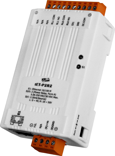
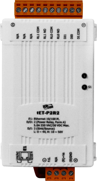
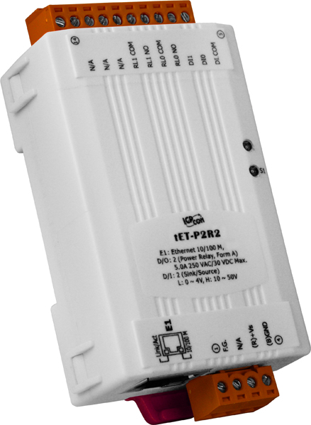
 Providing various digital I/O functions, the tET/tPET series is an IP-based Ethernet I/O monitoring and control module. The module can be remotely controlled through a 10/100 M Ethernet network by using Modbus TCP protocol. Modbus has become a de facto standard communications protocol in industry, and is now the most commonly available means of connecting industrial electronic devices. This makes the tET/tPET series perfectly integrate with the HMI, SCADA, PLC and other software systems.
The functionality of the tET/tPET series is almost the same as the ET-7000/PET-7000 series. The tET/tPET series tiny Ethernet I/O modules support various I/O types, like photo-isolated digital input, relay contact, photoMOS relay, and open-collector output. The module can be used to create DI to DO pair-connect through the Ethernet. Once the configuration is completed, the tET/tPET series module can poll the status of the local DI channels and then use the Modbus/TCP protocol to continuously write to a remote DO device in the background.
The tET/tPET series provides dual watchdog: CPU watchdog and host watchdog. The CPU watchdog automatically resets it-self when the built-in firmware runs abnormally. The host watchdog monitors the host controller (PC or PLC), and the output of the module can go to predefined state (safe value) when the host fails.
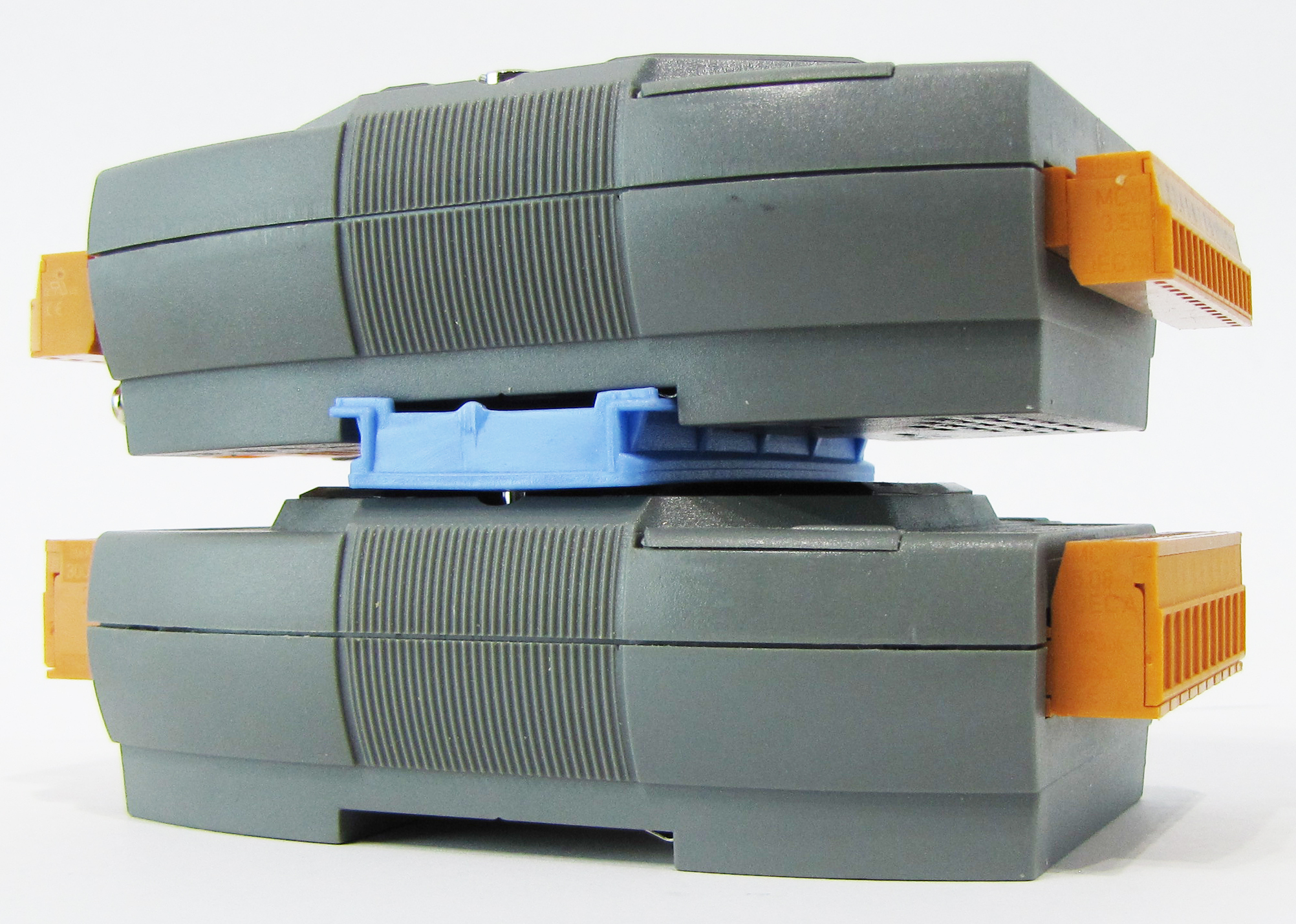
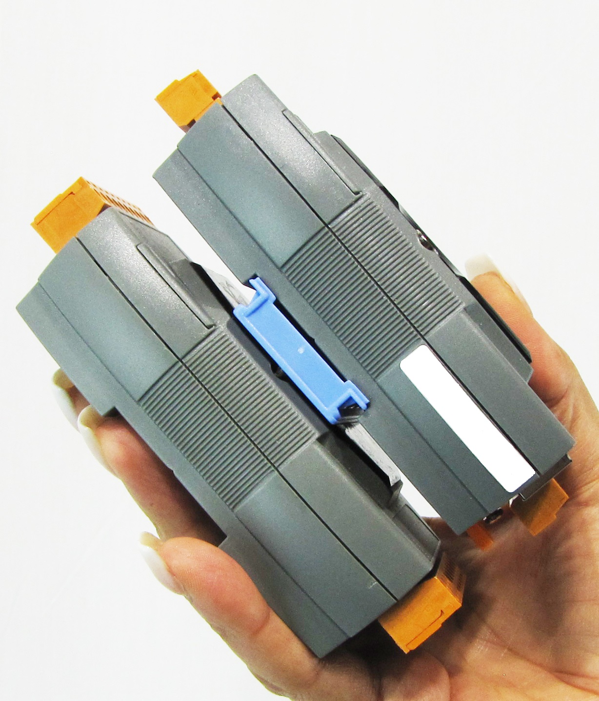
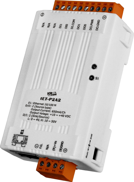
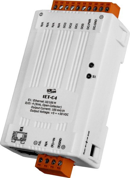
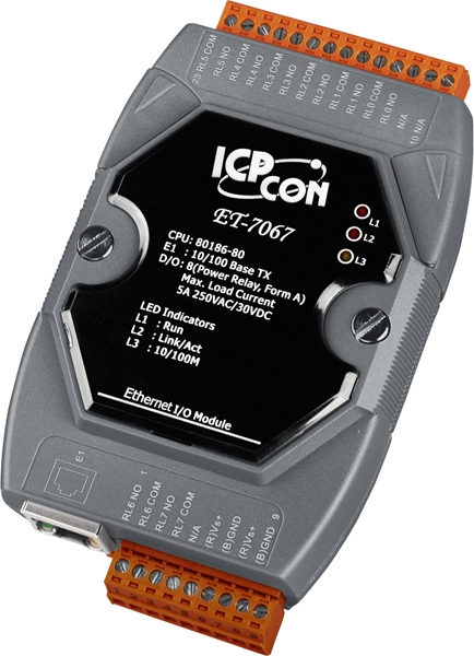
For maximum space savings, the tET/tPET series is offered in an amazing tiny form-factor that means it can be easily installed in anywhere, even directly embedded into a machine. It is equipped with two removable terminal block connectors for easy wiring, and features a powerful 32-bit ARM MCU to handle efficient network trafficking. The tPET series offers true IEEE 802.3af-compliant (classification, Class 1) Power over Ethernet (PoE) using a standard category 5 Ethernet cable to receive power from a PoE switch like the NS-205PSE. When there is no PoE switch on site, the tPET series accepts power input from DC adapter.
| Software | |
|---|---|
| Built-in Web Server | Yes |
| CPU Module | |
|---|---|
| CPU | 32-bit MCU |
| Watchdog Timer | Module, Communication (Programmable) |
| EMS Protection | |
|---|---|
| EFT (IEC 61000-4-4) | ±4 kV for Power Line |
| ESD (IEC 61000-4-2) | ±4 kV Contact for Each Terminal ±8 kV Air for Random Point |
| LED Indicators | |
|---|---|
| Status | Run, Ethernet |
| Digital Input/Counter | |
|---|---|
| Channels | 2 |
| Type | Wet Contact |
| Sink/Source (NPN/PNP) | Sink/Source |
| ON Voltage Level | +10 to +50 VDC |
| OFF Voltage Level | +4 VDC (max.) |
| Max. Counts | 4,294,967,295 (32-bit) |
| Frequency | 3.5 kHz (without filter) |
| Min. Pulse Width | 0.15 ms |
| Isolation | 3750 Vrms |
| Input Impedance | 10 k |
| Overvoltage Protection | +70 VDC |
| Relay Output | |
|---|---|
| Channels | 2 |
| Type | Power Relay, Form A (SPST N.O.) |
| Contact Rating | 5.0 A/channel at 25°C |
| Operate Time | 6 ms |
| Release Time | 3 ms |
| Electrical Endurance | 5 A 250 VAC 30,000 ops (10 ops/minute) at 75 °C 5 A 30 VDC 70,000 ops (10 ops/minute) at 75 °C 5 A 250 VAC/30 VDC 6,000 ops 3 A 250 VAC/30 VDC 100,000 ops |
| Mechanical Endurance | 20,000,000 ops. At no load (300 ops./minute) |
| Isolation | 3000 Vrms |
| Ethernet | |
|---|---|
| Ports | 1 x RJ-45, 10/100 Base-Tx |
| Access Control | Password and IP Filter |
| Protocol | Modbus TCP, Modbus UDP, and MQTT |
| Power | |
|---|---|
| Reverse Polarity Protection | Yes |
| Consumption | 0.8 W |
| Powered from Terminal Block | +12 to +48 VDC |
| Mechanical | |
|---|---|
| Dimensions (mm) | 52 x 95 x 27 (W x L x H) |
| Installation | DIN-Rail mounting |
| Environment | |
|---|---|
| Operating Temperature | -25 ~ +75 °C |
| Storage Temperature | -30 ~ +80 °C |
| Humidity | 10 to 90% RH, Non-condensing |
Our mission is to provide the absolute best customer experience in industrial automation and electronics, without exception.


Subscribe to our mailing list today and join thousands of others who want to stay up-to-date with the latest news in data acquisition and industrial data communication.
ICP DAS USA is a leading manufacturer of industrial data acquisition, data communication, programmable controllers, wireless and software solutions.
 Citect Application
 eSearch Utility
 EZ Data Logger Software
 3D STEP Model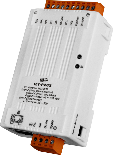
Add a review
Your email address will not be published. Required fields are marked *