
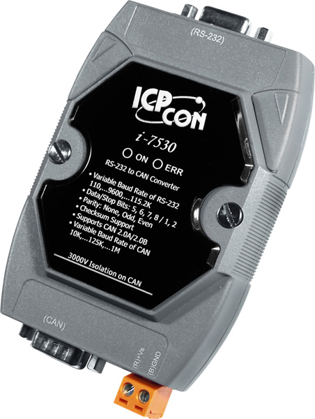
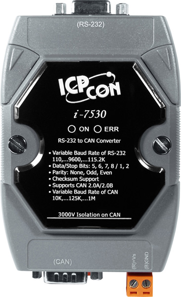
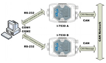
 In pair connection mode, I-7530 can be used to connect PC with other RS-232 devices at the same time. I-7530 can also enable programmable RS-232 devices such as PC's, I-8411/I-8431/I-8811/I-8831 embedded controllers to be the master of a CAN network.
3000V isolation on CAN side
The CAN port of I-7530 is an isolated with 3000V isolation. This isolation can protect the local RS-232 devices from the damage signal coming from CAN network.
Watchdog inside
The watchdog is a hardware reset circuit to monitor the operation status. When working in harsh or noisy environment, the I-7530/I-7530-FT may shut down by the external signal. The circuit may let the I-7530/I-7530-FT to work continuously and never halt.
Power and Error indicator display
There are two indicators on the I-7530/I-7530-FT.The power indicator can help user to check whether the I-7530/I-7530-FT is standby or transmitting/receiving messages. The Error indicator will be turned on when some errors occur on the I-7530/I-7530-FT.

There are various communication interfaces among the CAN devices like PCI CAN board, Ethernet series and RS-232 series CAN module. According to different purpose of users’ projects, the users maybe need to choice different CAN products. Because of this situation, the programmer should develop different communication program to handle different CAN device. For example, the user should develop “Socket Client” to communicate with I-7540. When using I-7530, the users need “UART” technique to communicate with it. Nowadays, ICP DAS develop the Virtual CAN technique. The Virtual CAN driver is the excellent tool for users. It transforms whole CAN devices into Virtual CAN port. And then it generates Virtual CAN port like “VxCAN 1” or “VxCAN 2”. The users could send and receive CAN message by appointing the Virtual CAN port number. The users don't need to care about what kind of CAN device which is used.


CAN Interface |
||
Transceiver |
NXP 82C250 |
AMIS 41682 |
Channel number |
1 |
|
Connector |
9-pin male D-Sub (CAN_L, CAN_H, N/A for others) |
|
Baud Rate (bps) |
10 k, 20 k, 50 k, 125 k, 250 k, 500 k, 800 k, 1 Mbps |
10 k, 20 k, 50 k, 125 kbps |
Isolation |
3000 VDC for DC-to-DC, 2500 Vrms for photo-couple |
NONE |
Terminator Resistor |
Selectable 120Ω terminator resistor by jumper |
1 kΩ for CAN_H and CAN_L |
Specification |
ISO-11898-2, CAN 2.0A and CAN 2.0B |
ISO-11898-3 (low speed fault tolerance), CAN 2.0A and CAN 2.0B |
Receive Buffer |
1000 data frames |
|
RS-232 Interface |
||
Connector |
9-pin female D-Sub (TxD, RxD, GND, N/A for others ) |
|
Baud Rate (bps) |
110, 150, 300, 600, 1200, 2400, 4800, 9600, 19200, 38400, 57600, 115200bps |
|
Data bit |
5, 6, 7, 8 |
|
Stop bit |
1, 2 |
|
Parity bit |
None, Even, Odd |
|
Receive Buffer |
900 data frames |
|
LED |
||
Round LED |
ON LED: Power and Data Flow; ERR LED: Error Status |
|
Power |
||
Protection |
Power reverse polarity protection, Over-voltage brown-out protection |
|
Power Consumption |
1 W |
|
Mechanism |
||
Installation |
DIN-Rail |
|
Dimensions |
72mm x 118mm x 33mm (W x L x H) |
|
Environment |
||
Operating Temp. |
-25 ~ 75 ℃ |
|
Storage Temp. |
-30 ~ 80 ℃ |
|
Humidity |
10 ~ 90% RH, non-condensing |
|
Our mission is to provide the absolute best customer experience in industrial automation and electronics, without exception.


Subscribe to our mailing list today and join thousands of others who want to stay up-to-date with the latest news in data acquisition and industrial data communication.
ICP DAS USA is a leading manufacturer of industrial data acquisition, data communication, programmable controllers, wireless and software solutions.
 User's Manual
 Software
 Wire
Wire Pin Assignment
 Block Diagram
Add a review
Your email address will not be published. Required fields are marked *