
| Share On: | |
|---|---|
| Categories: | CAN Communication Converters | CANBus Converters and Gateways |
| Review: | Write your review |
| Resources: |

The VxComm technology can be used to simulate COM/CAN ports of the I-7540D to become a COM port of a PC . With the help of VxComm driver, users can access the remote COM/CAN ports of the I-7540 just as they would access the PC's COM port. The block diagram of data processes in I-7540D is given as follows:
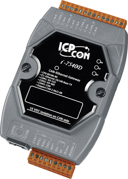
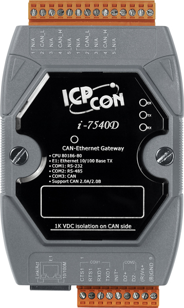
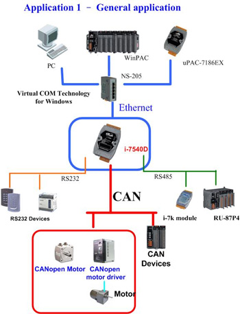
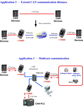
Internet communications using TCP/IP is increasing in the industrial sector. Using Ethernet for industrial networks is a good idea because the required cabling is already installed. The CAN-Ethernet Gateway from ICP DAS is a solution that enables CAN networks to be coupled together over the Internet via Ethernet, creating an environment where monitoring and control is possible. The CAN-Ethernet Gateway controls networked communications and creates a transparent CAN-based application interface.
The device supports a transparent, protocol-independent transfer of the CAN messages, thus allowing its implementation into a wide range of possible applications. Furthermore, the CAN-Ethernet Gateway can be used with various higher layer CAN protocols (e.g. CANopen, DeviceNet or other proprietary protocols). The following figure shows the application architecture for the CAN-Ethernet Gateway .
I-7540D can also be used as an Ethernet to CAN/RS-232/485 Device Server. The Device Server is an appliance that makes any device network enabled with a serial communication port. By virtue of its independent operating system, protocol independence, small size and flexibility, Device servers are able to meet the demand of virtually any network-enabled application. Most devices don't have network ports - I-7540D allows those devices to become connected to the network.
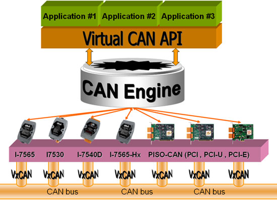
There are various communication interfaces among the CAN devices like PCI CAN board, Ethernet series, and RS-232 series CAN module. According to the different purposes of users’ projects, the users might need to choose different CAN products. Because of this situation, the programmer should develop different communication programs to handle different CAN devices. For example, the user could develop a “Socket Client” to communicate with I-7540. When using the I-7530, the users need “UART” techniques to communicate. Nowadays, ICP DAS develops the Virtual CAN technique. The Virtual CAN driver is an excellent tool for users. It transforms whole CAN devices into Virtual CAN ports. Then it generates Virtual CAN ports like “VxCAN 1” or “VxCAN 2”. The users could then send and receive CAN message by appointing a Virtual CAN port number. The users don't need to figure out what kind of CAN device is used.
| The test is the performance which transfer 8 bytes data frame from CAN to Ethernet (one TCP client). | ||||||||
| CAN setting | Transfer frames | Transfer time(ms) | Ethernet setting | Receive frames | Receive time (ms) | The max frames/sec | Data<8 byes/frme | ASCII command length |
| 2.0A 1Mbps | 1,000,000 | 619,831 | 100M | 1,000,000 | 619,871 | 1613 | >=1613 | 22 B |
| 2.0B 1Mbps | 1,000,000 | 662,432 | 100M | 1,000,000 | 662,513 | 1509 | >=1509 | 27 B |
| The test is the performance which transfer 8 bytes data frame from Ethernet (one TCP client) to CAN. | ||||||||
| CAN setting | Transfer frames | Transfer time (ms) | Ethernet setting | Receive frames | Receive time (ms) | The max frames/sec | Data<8 byes/frame | ASCII command length |
| 2.0A 1Mbps | 1,000,000 | 535,280 | 100M | 1,000,000 | 535,618 | 1867 | >=1867 | 22 B |
| 2.0B 1Mbps | 1,000,000 | 563,170 | 100M | 1,000,000 | 563,395 | 1774 | >=1774 | 27 B |
| LED Indicators | |
|---|---|
| Status | 1 x Power 3 x CAN status |
| Ethernet | |
|---|---|
| Ports | 1 x RJ-45, 10/100Base-T(X) |
| COM Ports | |
|---|---|
| Ports | 1 x RS-232 1 x RS-485 (self-turner ASIC inside) |
| Baud Rate | 110, 150, 300, 600, 1200, 2400, 4800, 9600, 19200, 38400, 57600, 115200 bps |
| Parity | None, Even, Odd |
| Data Bit | 7, 8 |
| Stop Bit | 1 |
| CAN | |
|---|---|
| Controller | NXP SJA1000T with 16 MHz clock |
| Ports | 1 |
| Specification | ISO-11898-2, CAN 2.0A and CAN 2.0B |
| Baud Rate | 10 k ~ 1 M bps |
| Isolation | 1000 VDC for DC-to-DC, 2500 Vrms for photo-couple |
| Terminal Resistor | Jumper for 120 terminal resistor |
| Filter | Yes |
| Power | |
|---|---|
| Input Range | +10 VDC ~ +30 VDC |
| Consumption | 2.5 W |
| Mechanical | |
|---|---|
| Casing | Plastic |
| Dimensions (mm) | 72 x 122 x 33 (W x L x H) |
| Installation | DIN-Rail |
| Environment | |
|---|---|
| Operating Temperature | -25 ~ +75 °C |
| Storage Temperature | -30 ~ +80 °C |
| Humidity | 10 ~ 90% RH, Non-condensing |
Our mission is to provide the absolute best customer experience in industrial automation and electronics, without exception.


Subscribe to our mailing list today and join thousands of others who want to stay up-to-date with the latest news in data acquisition and industrial data communication.
ICP DAS USA is a leading manufacturer of industrial data acquisition, data communication, programmable controllers, wireless and software solutions.
 Data Sheet
 Hardware
 Software
 Wire Connections
 2D DWG Drawing
Add a review
Your email address will not be published. Required fields are marked *