

| Share On: | |
|---|---|
| Categories: | CAN Communication Converters | CANBus Converters and Gateways |
| Review: | Write your review |
| Resources: |

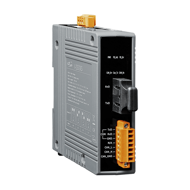
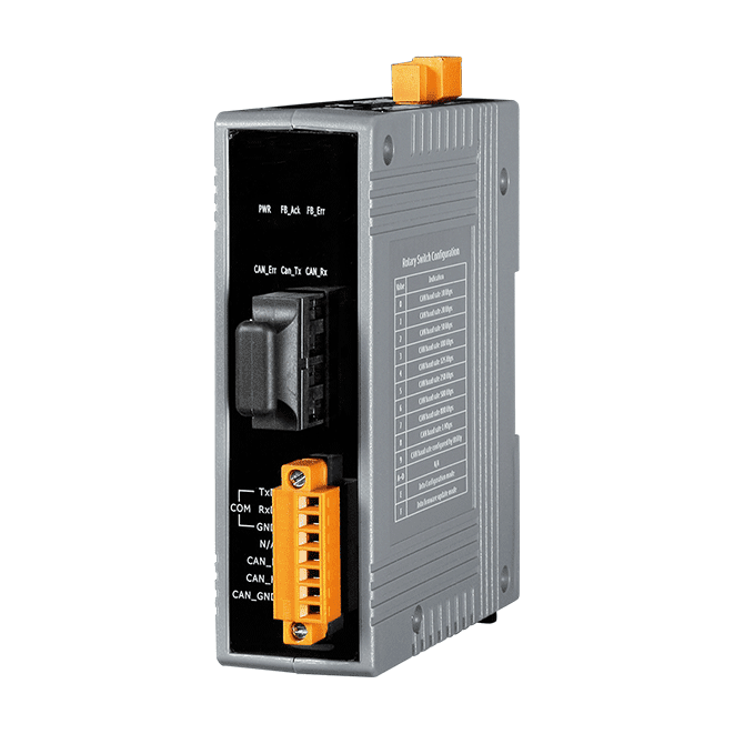
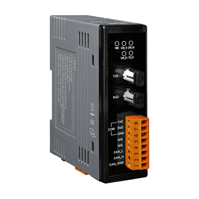
The I-2533CS is a local CAN bridge used to establish a connection between two CAN bus systems via single mode fiber optic transmission medium. The I-2533CS series is specially designed for converting the electrical CAN bus signal to fiber optic communication for transmission over single mode fiber optic cables.
The transmission distance limitation of the CAN bus system will not be affected due to different CAN baud rates. The total CAN bus communication distance can be extended over fiber optic cables. Bus errors on one CAN network will not affect the operation of another CAN network. Two CAN networks can communicate with each other by using different CAN baud rates for flexibility.

The I-2533CS is designed for single mode fiber, and can allow to extend the CAN bus to a maximum 30 km. I-2533CS provides the group function, which is a basic message router. Users can decide the CAN message flow between several CAN bus systems. I-2533CS comes with a utility tool for user-defined baud rate and CAN message filter configuration. With two I-2533CS series on two CAN networks with different CAN baud rates, it may be useful to reduce the bus loading of the network which has a low baud rate.
Building Automation, Factory Automation, Machine Automation, Remote Maintenance, Remote diagnosis and Testing Equipment, etc.
| LED Indicators | |
|---|---|
| Status | 1 x Power 3 x CAN status 2 x Fiber status |
| COM Ports | |
|---|---|
| Ports | 1 x RS-232 (Utility Port) |
| Fiber | |
|---|---|
| Ports | Single-Mode; SC Duplex connector x 1; 100 Base-FX |
| Fiber Cable | 8.3/125, 8.7/125, 9/125 or 10/125 m |
| Wavelength | 1310 nm |
| TX Output | -15 dBmMin. , -8 dBm Max. |
| Transmission Distance | 30 km (9/125 m recommended) |
| RX Sensitivity | -34 dBm Max. |
| RX Overload | -5 dBm Max. |
| Budget | 19 dBm |
| Propagation Delay | 190 us (Note1) |
| CAN | |
|---|---|
| Ports | 1 |
| Specification | ISO 11898-2, CAN 2.0A and CAN 2.0B |
| Baud Rate | 10 k ~ 1 M bps |
| Isolation | 500 Vrms on the CAN side |
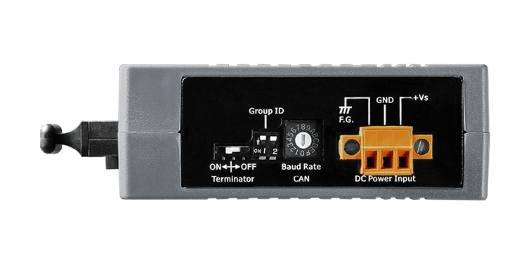
| Terminal Resistor | Switch for 120 terminal resistor |
| Filter | Yes |
| Power | |
|---|---|
| Input Range | +10 VDC ~ +30 VDC |
| Consumption | 3 W |
| Mechanical | |
|---|---|
| Casing | Plastic |
| Dimensions (mm) | 33 x 126 x 101 (W x L x H) |
| Installation | DIN-Rail |
| Environment | |
|---|---|
| Operating Temperature | -25 ~ +75 °C |
| Storage Temperature | -30 ~ +80 °C |
| Humidity | 10 ~ 90% RH, Non-condensing |
Note1: The propagation delay depends on the CAN Bus baud rate and the CAN message format. This value has been tested using a CAN baud rate of 1 Mbps, the CAN ID 0x12345678 and 8 bytes of data with a value of 0xFF.
Our mission is to provide the absolute best customer experience in industrial automation and electronics, without exception.


Subscribe to our mailing list today and join thousands of others who want to stay up-to-date with the latest news in data acquisition and industrial data communication.
ICP DAS USA is a leading manufacturer of industrial data acquisition, data communication, programmable controllers, wireless and software solutions.
 Data Sheet
 Download Firmware Update Tool
 Download Software Utility
 2D DWG Drawing

Add a review
Your email address will not be published. Required fields are marked *