
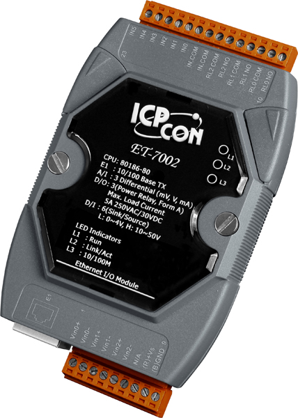
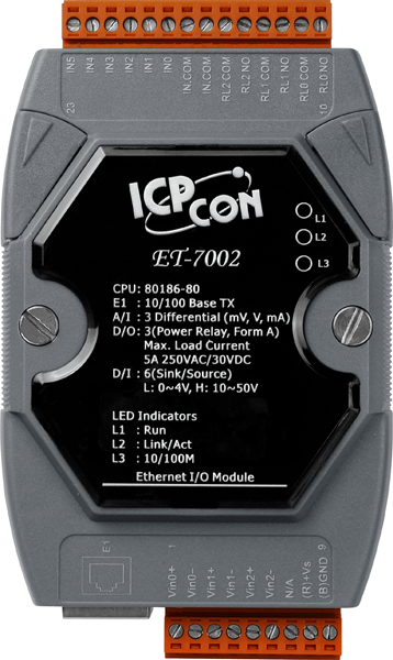
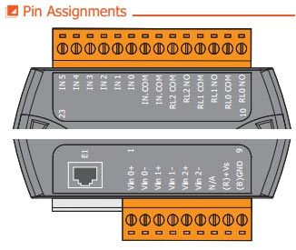
 The ET-7002 is a web-based Ethernet I/O module that features a built-in web server which allows remote configuration, I/O monitoring and I/O control simply by using a regular web browser. Remote control is as easy as surfing the Internet. In addition, the web HMI function means that programming or HTML skills are no longer required so creating dynamic and attractive web pages for I/O monitoring and I/O control purposes will be easy for engineers in the future. The ET-7002 offers easy and safe access for users at anytime and from anywhere, and also supports the Modbus/TCP protocol that ensures perfect integration with SCADA software.
The ET-7002 is a multi-function module provides 3 analog input channels, 6 digital input channels and 3 relay output channels. A programmable input range is provided on all analog inputs (+/- 150 mV, +/-500 mV, +/-1 V, +/-5 V, +/-10 V, +/-20 mA, 0~20 mA and 4~20 mA). The range for each analog input can be configured individually and each input has a high overvoltage protection of 240Vrms. The analog inputs are also jumper selectable for either voltage or current inputs. The ET-7002 is fully RoHS-compliant and provides 4 kV ESD protection, 3 kV surge protection as well as 2500 VDC intra-module isolation.
Building Automation, Factory Automation, Machine Automation, Remote Maintenance, Remote diagnosis, Testing Equipment.
| Software | |
|---|---|
| Built-in Web Server | Yes |
| CPU Module | |
|---|---|
| Watchdog Timer | Module, Communication (Programmable) |
| Isolation | |
|---|---|
| 2-way Isolation | Ethernet: 1500 VDC I/O: 2500 VDC |
| EMS Protection | |
|---|---|
| EFT (IEC 61000-4-4) | 4 kV for Power Line |
| ESD (IEC 61000-4-2) | 4 kV Contact for Each Terminal 8 kV Air for Random Point |
| Surge (IEC 61000-4-5) | 0.5 kV for Power Line |
| LED Indicators | |
|---|---|
| Status | Run, Ethernet |
| Analog Input | |
|---|---|
| Channels | 3 (Differential) |
| Type | Voltage Current |
| Range | 150 mV, 500 mV, 1 V, 5 V, 10 V 0 to 20 mA, 20 mA, 4 to 20 mA (Jumper Selectable) |
| Resolution | 16-bit |
| Accuracy | Normal Mode: 0.1% Fast Mode: 0.5% or better |
| Sampling Rate | Normal Mode: 10 Hz (total channels) Fast Mode: 50 Hz (total channels) |
| Input Impedance | Voltage: 2 M Current: 125 |
| Overvoltage Protection | 240 Vrms |
| Overcurrent Protection | 50 mA @ 110 VDC (max.) |
| Individual Channel Configuration | Yes |
| Open Wire Detection | For 4 to 20 mA only |
| Isolation | 400 VDC, Virtual Channel to Channel Isolation |
| Digital Input/Counter | |
|---|---|
| Channels | 6 |
| Type | Wet Contact |
| Sink/Source (NPN/PNP) | Sink/Source |
| ON Voltage Level | +10 to +50 VDC |
| OFF Voltage Level | +4 VDC (max.) |
| Max. Counts | 4,294,967,295 (32-bit) |
| Frequency | 100 Hz |
| Min. Pulse Width | 5 ms |
| Input Impedance | 10 K, 0.5W |
| Overvoltage Protection | +70 VDC |
| Relay Output | |
|---|---|
| Channels | 3 |
| Type | Power Relay, Form A (SPST N.O.) |
| Contact Rating | 5 A @ 250 VAC/24 VDC (Resistive Load) |
| Operate Time | 6 ms (Typical) |
| Release Time | 3 ms (Typical) |
| Electrical Endurance | 105 ops. |
| Mechanical Endurance | 2 107 ops. |
| Power on Value | Programmable |
| Safe Value | Programmable |
| Ethernet | |
|---|---|
| Ports | 1 x RJ-45, 10/100 Base-TX |
| Access Control | ID, Password and IP Filter |
| Protocol | Modbus TCP, Modbus UDP |
| Power | |
|---|---|
| Reverse Polarity Protection | Yes |
| Consumption | 2.9 W (max.) |
| Powered from Terminal Block | +10 to +30 VDC |
| Mechanical | |
|---|---|
| Dimensions (mm) | 72 x 123 x 35 (W x L x H) |
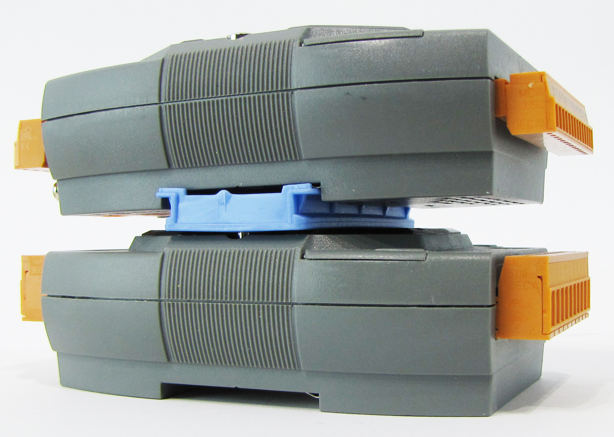
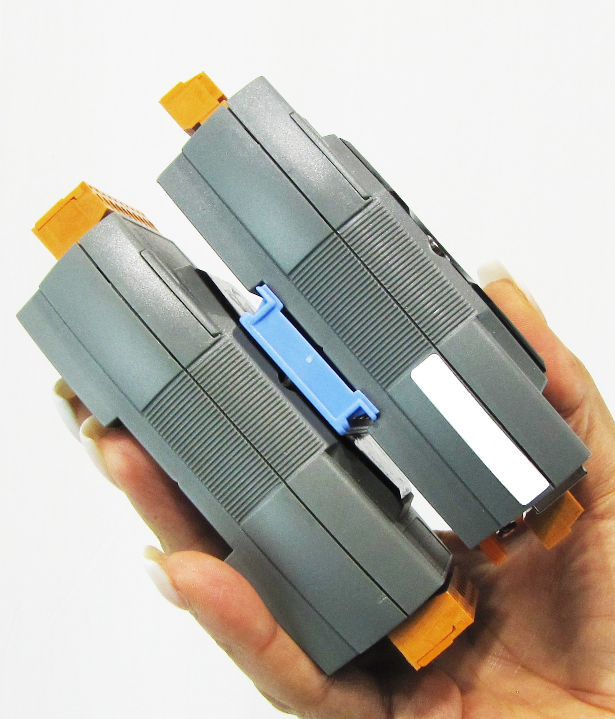
| Installation | DIN-Rail mounting |
| Environment | |
|---|---|
| Operating Temperature | -25 +75 C |
| Storage Temperature | -30 +80 C |
| Humidity | 10 to 90% RH, Non-condensing |
Our mission is to provide the absolute best customer experience in industrial automation and electronics, without exception.


Subscribe to our mailing list today and join thousands of others who want to stay up-to-date with the latest news in data acquisition and industrial data communication.
ICP DAS USA is a leading manufacturer of industrial data acquisition, data communication, programmable controllers, wireless and software solutions.
 Data Sheet
 Free EZ Data Logger Software
 2D DWG Drawing
Add a review
Your email address will not be published. Required fields are marked *