
PACs in a Railway Signaling Application

Application Overview
A railway signaling system is a series of chain control systems. If one device fails, additional back-end devices may also fail, which can make troubleshooting difficult because maintenance personnel may need to check each device individually to determine where the failure began.
A railway signaling monitoring and control system centralizes management and monitoring so signaling data can be collected, analyzed, and used to trace the source of a problem. Device failures can be detected in real time, supporting railway safety, train punctuality, and maintenance work.
The Challenge
Railway signaling systems combine communication, digital, and analog information from many devices. When a failure occurs, the final failure result may not immediately identify the original source, making it difficult for maintenance personnel to isolate the affected device.
The system therefore needs to collect signaling information from field equipment, transmit it through the network, and present it through a centralized graphical interface so operators can monitor operating conditions, analyze data, and trace problems more efficiently.
The ICP DAS USA’s Solution
The railway signaling monitoring and control system includes three parts: a signal converter, a SCADA system, and a signal processing and control unit. ICP DAS USA’s WinPAC-8000 series PACs are used for signal processing and control.
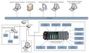
Signal Processing and Control Unit
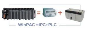
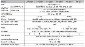
A WinPAC-8000 series PAC is used for signal processing and control. The platform provides a high-performance CPU, large-capacity memory and storage, and input/output interfaces including USB, VGA, Ethernet, RS-232, and RS-485. It also includes a real-time operating system and supports IEC 61131-3 control applications.
Programming options include Functional Block Diagram (FBD), Ladder Diagram (LAD), Sequential Function Chart (SFC), and Structured Text (ST).
The PAC can send and receive data through plug-in I/O modules such as the I-8014W analog input module, I-87053W isolated digital input module, and I-87057W isolated digital output module. The WinPAC also supports RS-232 and RS-485 communications, while the I-8144iW provides four isolated RS-422/RS-485 serial ports.
The information sent and received by the signal processing and control unit includes:
After the data is processed, the PAC can exchange information with the SCADA system, traffic control center, or central server via the Internet.
Signal Converter
The signal converter connects to Vital Processor Interlocking (VPI), Non-Vital Processor Interlocking (NVPI), and Visual Display Unit (VDU) modules through RS-422/RS-232 communication. It sends, receives, and exchanges information with the SCADA system, traffic control center, or central server.
The information includes Centralized Traffic Control (CTC) information, VDU information, Passenger Information Display System (PIDS) information, and communication information between train stations.
SCADA System
The SCADA system presents signal converter and signal processing and control information through graphical pages. The main page can include real-time data, accumulated data, and data-analysis charts.
Additional pages can provide alarm management for real-time and historical data, statistics and analysis reports, parameter settings for critical values, database management, system operation parameter settings, and replay of track operations. Operators can access the information from the control room or through a remote network.
The real-time information page can display the railway route as a graphical diagram together with station connection status. Monitoring information can include the speed code for each track circuit, the working current of the track circuit, and the reverse current value of the switch on the route map.
The accumulated data page can store error-message logs, time charts for working current on each track circuit, and track-operation replay. After troubleshooting an abnormal track operation, the replay function can be used to review the event and help verify the source of the problem. Track operations can be replayed at full, half, or double speed.
The data-analysis chart page can also be used for warning analysis. For example, manufacturer-provided railroad switch motor data can be compared with real-time detected motor data. When customer-defined threshold criteria are exceeded, the system can issue a warning so relevant personnel can inspect, repair, or replace affected parts.
How the System Works
Key Benefits
Conclusion
A railway signaling monitoring and control system provides a centralized way to collect, process, display, and analyze information from signaling equipment. By combining a signal converter, SCADA system, and WinPAC-8000 series PAC for signal processing and control, operators and maintenance personnel can monitor device status, review historical data, manage alarms, and trace abnormal conditions more efficiently.
The system supports real-time failure detection, track-operation replay, warning analysis, and centralized access to railway signaling information, helping improve maintenance efficiency and the reliability of railway signaling operations.


