
| Share On: | |
|---|---|
| Categories: | Modbus Converters | HART Converters and Gateways Data Communication | Modbus Converters and Gateways | HART Converters and Gateways |
| Review: | Write your review |
| Resources: |  Quick Start
User Manual
Data Sheet Quick Start
User Manual
Data Sheet
 Download Software Utility
PIN Assignment Download Software Utility
PIN Assignment
|
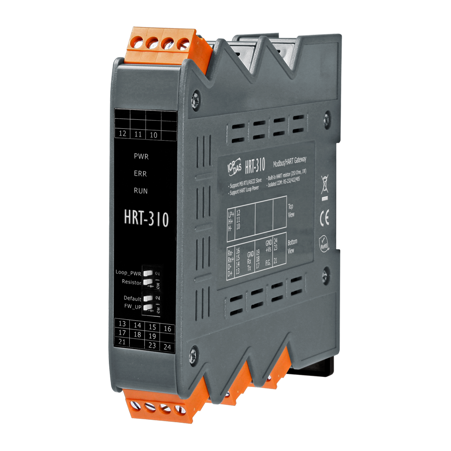
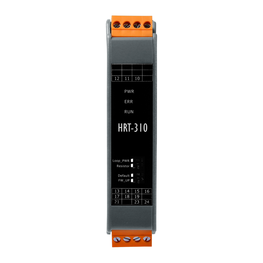
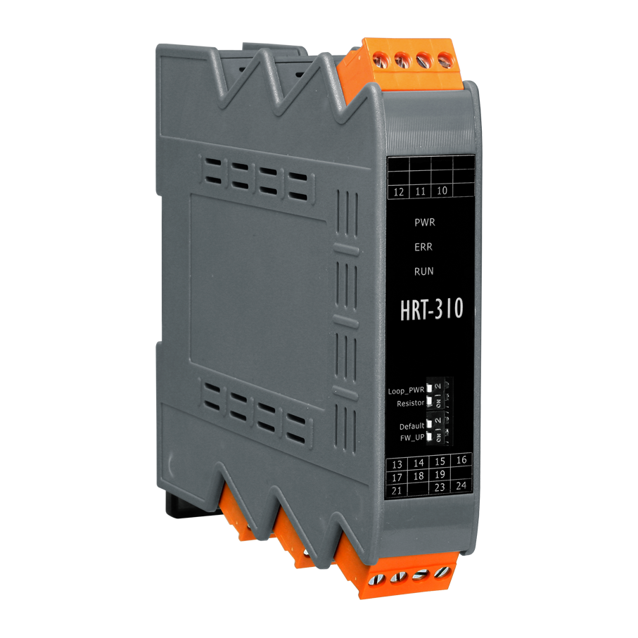
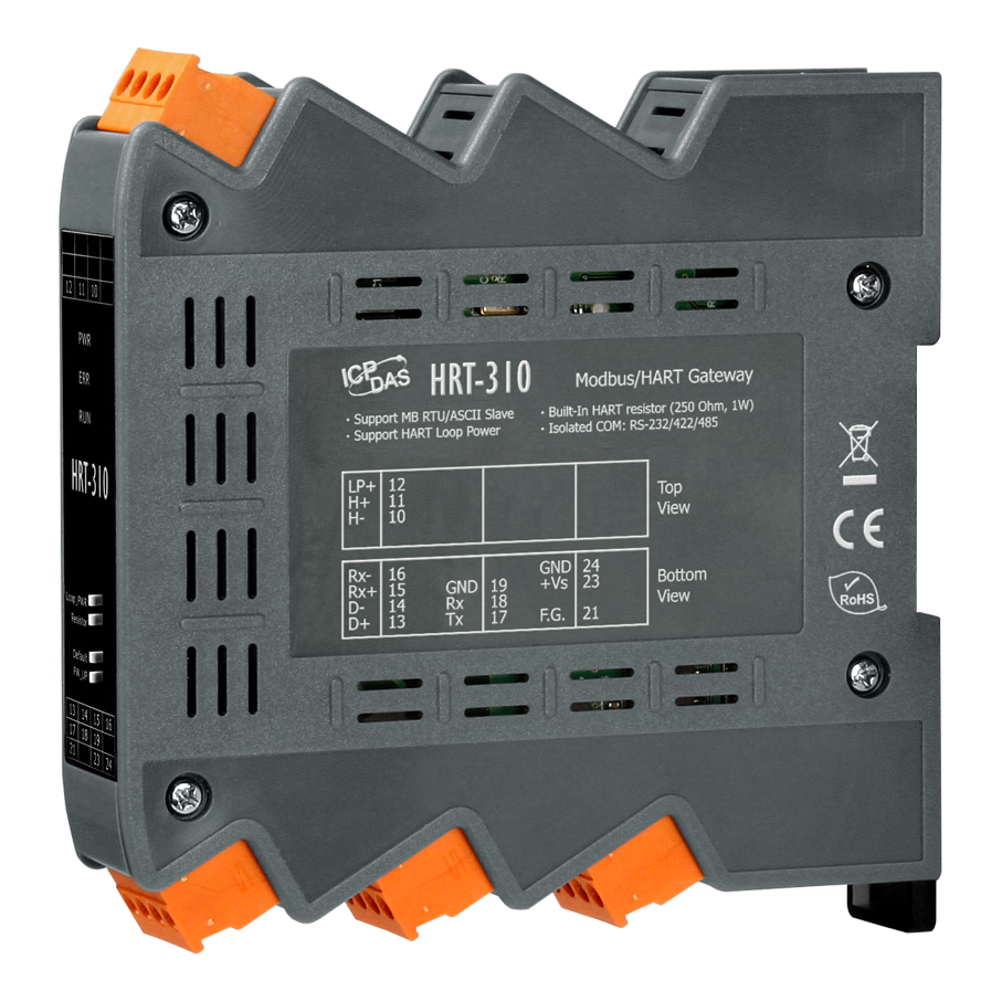
The HRT-310 is designed to be used as a master device of HART protocol, allowing the Modbus to connect HART devices and converting the HART protocol to Modbus RTU / ASCII protocol. In addition, the gateway is equipped with a more powerful built-in resistor, allowing connecting up to 15 HART devices without having to connect an additional external resistor. The HRT-310 is designed for users to integrate their HART devices into Modbus network easily and quickly.


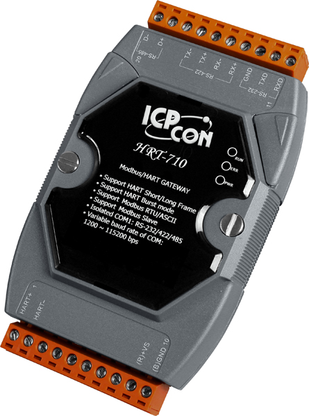
HRT-710
HRT-310
HRT-710
Horizontal
HRT-310
Upright
HRT-710
Standard
HRT-310
Enhanced send/receive signal (For long distance comm.)
HRT-710
No
HRT-310
Support (module provides +30V output)
HRT-710
250 Ohm (1/4W)
HRT-310
250 Ohm (1W)


HRT-310, a HART master to Modbus slave gateway, is applied to integrate the information from these HART flow meters into the customer's HMI system. Through the HRT-310, all of the HART flow meters will be regarded as Modbus slave devices and the HMI system can use the built-in Modbus RTU communication to access these HART flow meters easily.

More than 250 HART device information needs to be integrated to surveillance center. In PC side, uses 3 pieces of PCI cards (VXC-148U, for 24 channels RS-485 expansion). I-2542A and I-2542B (RS-485 to Fiber) are used in every RS-485 channel to extend RS-485 communication distance. There are about 20 pieces of HRT-710 modules used in every RS-485 channel with the different station ID. Through the structure, SCADA or HMI system can integrate all HART device information via Modbus protocol easily and quickly.

Code
Name
Description
Code
Name
Read Coil Status
Description
Read the ON/OFF status of discrete outputs in the slave
Code
Name
Read Input Status
Description
Read the ON/OFF status of discrete inputs in the slave
Code
Name
Read Holding Registers
Description
Read the binary contents of holding registers in the slave
Code
Name
Read Input Registers
Description
Read the binary contents of input registers in the slave
Code
Name
Force Single Coil
Description
Write a single output to either ON or OFF in the slave
Code
Name
Preset Single Register
Description
Write an integer value into a single register in the slave
Code
Name
Force Multi. Coils
Description
Write each coil in the sequence of coils to either ON or OFF in the slave
Code
Name
Preset Multi. Registers
Description
Write a block of contiguous registers in the slave
UART Interface
COM Port
RS-232(3 wires) / RS-422 / RS-485
Baud Rate (bps)
1200, 2400, 4800, 9600, 19200, 38400, 57600, 115200
Protocol
Modbus RTU / Modbus ASCII
Connector
4-pin screwed terminal block
HART Interface
HART Channel
1
HART Interface
2-pin screwed terminal block
HART Device
2-wired or 4-wired HART devices
HART Topology
Point to Point or Multi-Drop
HART Data
Only Digital Data
HART Frame Type
Short and Long Frame
Burst Mode
Supported
Max. HART Device
15
Isolation
UL1577 Spec.
Loop Resistor
250 Ω (1W) by Dip-Switch
Loop Power
Yes (module provides +30V output)
Power
Power supply
Unregulated +10 ~ +30 VDC
Protection
Power reverse polarity protection, Over-voltage brown-out protection
Power Consumption
3.5W (Max.)
Mechanism
Installation
DIN-Rail (Upright)
Dimensions
25 mm x 116 mm x 120 mm (W x L x H)
Environment
Operating Temp.
-25°C ~ +75°C
Storage Temp.
-30°C ~ +80°C
Humidity
5% ~ 95% RH, non-condensing
Our mission is to provide the absolute best customer experience in industrial automation and electronics, without exception.


Subscribe to our mailing list today and join thousands of others who want to stay up-to-date with the latest news in data acquisition and industrial data communication.
ICP DAS USA is a leading manufacturer of industrial data acquisition, data communication, programmable controllers, wireless and software solutions.
Add a review
Your email address will not be published. Required fields are marked *