
| Share On: | |
|---|---|
| Categories: | CANopen Data Acquisition | New Products |
| Review: | Write your review |
| Resources: |
CANopen is one kind of the network protocols based on the CAN bus and mainly used for embedded network of machine control, such as industrial machine control , aircraft engines monitoring, factory automation, medical equipments control, remote data acquisition, environmental monitoring, and packaging machines control, etc.
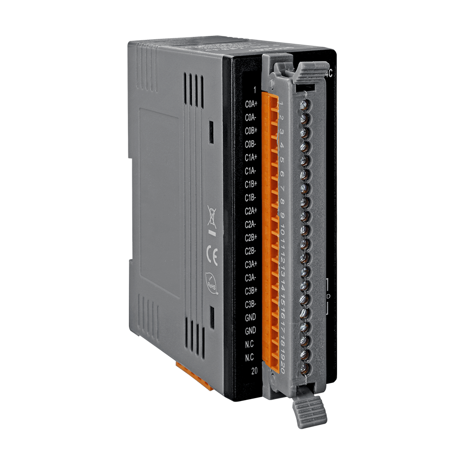
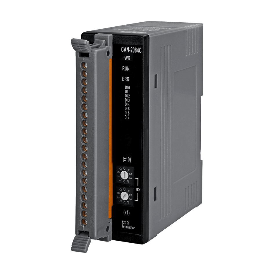
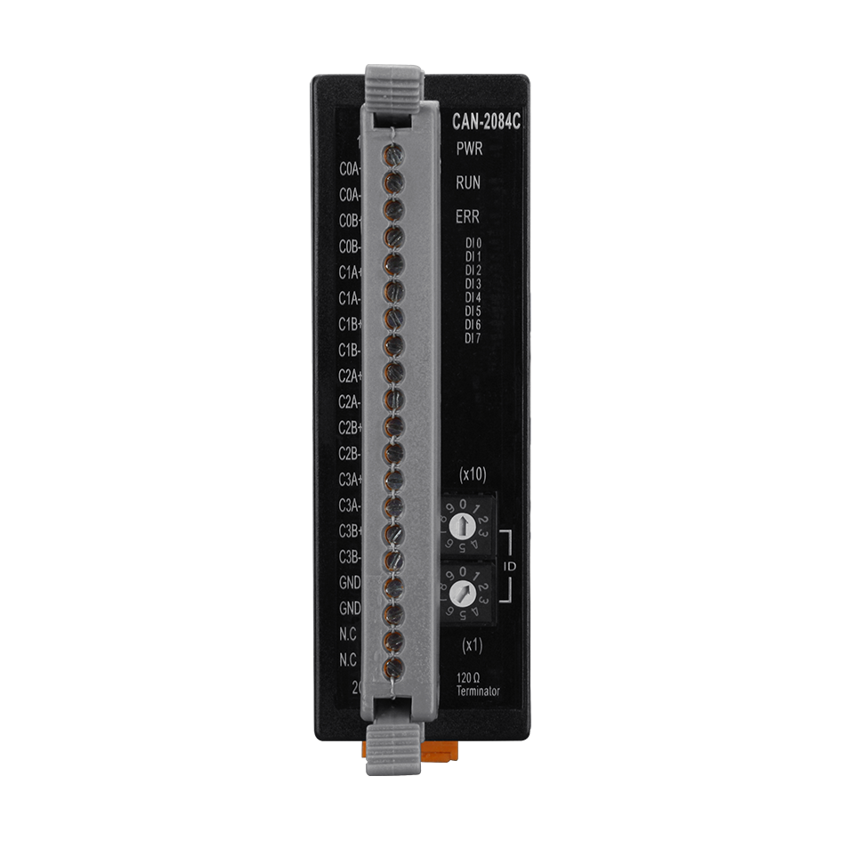
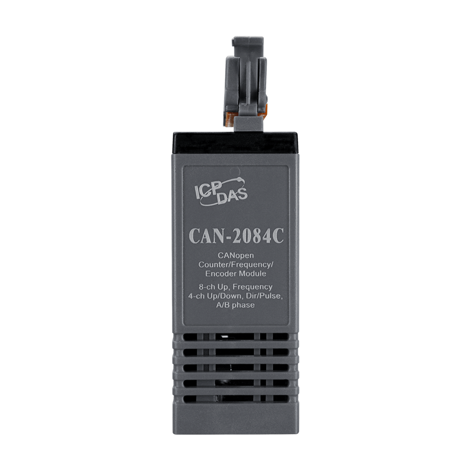
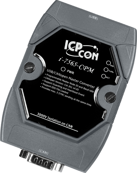
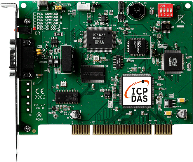
CAN-2084C module follows the CiA-301 version 4.02. CAN-2084C has passed the validation of the CiA CANopen conformance test tool. Therefore, you can use it with standard CANopen master easily by applying the EDS file. The CAN-2084C is a 4/8-channel Counter/Frequency module that provides “Up Counter”, "Frequency”, “Up/Down Counter”, “Dir/Pulse Counter” and “A/B Phase Counter” modes. It provides a variety of measurement applications, such as measuring a number of time-related quantities, counting events or totalizing and monitoring position with quadrature encoders. In addition, a digital filter is used to eliminate the effects of noise. By owing to the CANopen masters of ICP DAS, you can quickly build a CANopen network to approach your requirements. For more information about the CANopen master interfaces and other CANopen products, please refer to the following web site.
Applications

CANopen Interface
Connector
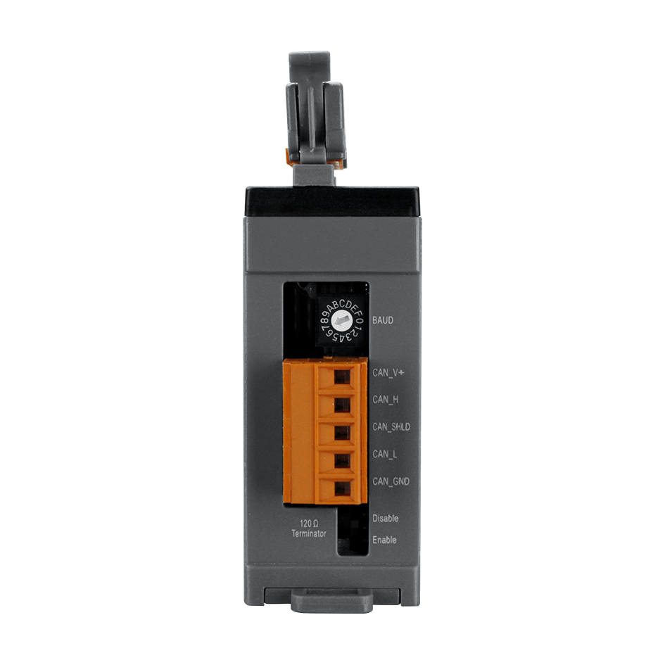
5-pin screwed terminal block (CAN_GND, CAN_L, CAN_SHLD, CAN_H, CAN_V+)
Baud Rate (bps)
10 k, 20 k, 50 k, 125 k, 250 k, 500 k, 800 k, 1 M, selected by rotary switch
Terminal Resistor
DIP switch for the 120Ω terminal resistor
Protocol
CANopen CiA 301 ver4.02, CiA 401 ver2.1
Node ID
1~99 selected by rotary switch
NMT
Slave
Error Control
Node Guarding protocol / Heartbeat Producer
SDOs
1 server, 0 client
PDOs
10 RxPDO, 10 TxPDO (Supports dynamic PDO)
PDO Modes
Event-triggered, remotely-requested, synchronous (cyclic), synchronous (acyclic)
Emergency Message
Yes
EDS file
Yes
Digital Input
Channels
4/8
Mode
4-channel Up/Down Counter (Up/Down)
4-channel Dir/Pulse Counter (Bi-direction)
4-channel Quadrant Counting
8-channel Up Counter
8-channel Frequency
Programmable Digital Noise Filter: 1 to 32767 µs
Isolated Input Level
Logic Level 0: +1 V Max.
Logic Level 1: +4.5 to +30 V
TTL Input Level
Logic Level 0: 0 to +0.8 V
Logic Level 1: 2 to +5 V
Minimum Pulse Width
2µs
Input Frequency
1 Hz ~ (typically) 250 kHz for both counter and frequency mode, where 250 kHz is calculated as follows:
supposed that the duty cycle = 50%, by referring to the Minimum Pulse Duration of the High Level, the pulse period will be 2 µs x 2 = 4 µs, which is 250 kHz as a maximum.
Maximum Frequency:
Refer to the Minimum Pulse Duration of the High Level, the maximum frequency is highly affected by the duty cycle
Frequency Accuracy = ±0.4%
EEPROM
128KB
Isolated Voltage
1000Vrms
Hardware
ESD Protection
2 kV (Contact for each Channel)
LED
CANopen Status
3 LEDs to PWR, RUN and ERR
Terminal Resister
1 LED to terminal resister indicator
Digital Input
8 LEDs as Digital Input Indicators
Power
Power Supply
Unregulated +10 ~ +30 VDC
Power Consumption
1.5 W
Mechanism
Dimensions
33 mm x 99 mm x 78 mm ( W x L x H )
Environment
Operating Temp.
-25 ~ 75°C
Storage Temp.
-30 ~ 80°C
Humidity
10 ~ 90% RH, non-condensing
Our mission is to provide the absolute best customer experience in industrial automation and electronics, without exception.


Subscribe to our mailing list today and join thousands of others who want to stay up-to-date with the latest news in data acquisition and industrial data communication.
ICP DAS USA is a leading manufacturer of industrial data acquisition, data communication, programmable controllers, wireless and software solutions.
 Data sheet
 Internal IO Structure
 PIN Assignment
 Wire Connection
Add a review
Your email address will not be published. Required fields are marked *